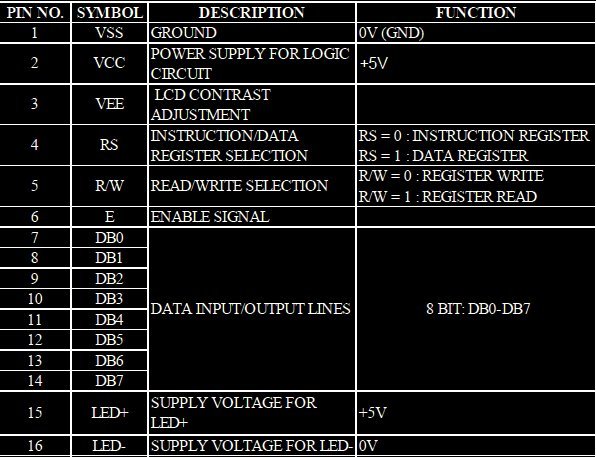
LCD INTERFACING WITH ARM
The 16x2 character LCD can also be used to display custom characters other than numerals, alphabets & special characters. Some special shapes like hearts, arrows, smileys etc. LCD can be easily interfaced with a microcontroller ARM LPC2148 to display a message or status of a device.
Synopsis

Several automated and semi-automated devices require a message to be displayed in order to indicate their working status.The 16x2 character LCD can also be used to display custom characters other than numerals, alphabets & special characters. Some special shapes like hearts, arrows, smileys etc. can easily be displayed on the 5x7 and 5x10 pixel pattern of character LCD. These shapes are first stored at a special location in LCD’s controller and then displayed on the LCD module. LCDs are easy to program and prove to be a better display unit as compared to other devices like seven-segments and LED display units. The reasons being: LCDs are economical, easily programmable. LCD can be easily interfaced with a microcontroller ARM LPC2148 to display a message or status of a device.

Description

ARM is one of the major options available for embedded system developer. LPC2148 is the widely used IC from ARM-7 family. It is manufactured by Philips and it is pre-loaded with many inbuilt peripherals making it more efficient and a reliable option for the beginners as well as high end application developer.

ARM is a family of instruction set architectures for computer processors based on a reduced instruction set computing (RISC) architecture developed by British company ARM Holdings .A RISC-based computer design approach means ARM processors require significantly fewer transistors than typical processors in average computers. This approach reduces costs, heat and power use. These are desirable traits for light, portable, battery-powered devices including smartphones, laptops, tablet and notepad computers and other embedded systems. A simpler design facilitates more efficient multi-core CPUs and higher core counts at lower cost, providing higher processing power and improved energy efficiency for servers and supercomputers.


The ARM LPC2148 features are as follows:

1. Architecture: ARM v4T

2. Processor: ARM7-TDMI-S

3. Instructions: 32-bit ARM and 16-bit Thumb

4. Debug support: RT Embedded ICE, Embedded Trace interface

5. Static RAM: 32 KB

6. (On-chip)Additional: 8 KB for USB DMA

7. Flash Program: 512 KB

8. Mem.(On-chip)Programming: ISP/IAP via on-chip boot-loader program

9. GPIO No. of pins: up to 45 (fast GPIO lines, 5V tolerant), Configurable to fast GPIO

10. External Interrupts: Four; No. of pins: Nine

The ARM LPC2148 has two ports Port 0 and Port 1 respectively each port contains 32-bits for I/O operations. The Port 0 has 32-bit of I/O pins for individual directions and Port 1 has 32-bits of I/O pins for bidirectional purpose. It has two timers of each 32-bit. It has capable to storing 128-bit memory for interfacing.

Over the last few years, the ARM architecture has become the most pervasive 32-bitarchitecture in the world, with wide range of ICs available from various IC manufacturers. ARM processors are embedded in products ranging from cell/mobile phones to automotive braking systems. A worldwide community of ARM partners and third-party vendors has developed among semiconductor and product design companies, including hardware engineers, system designers, and software developers.

Liquid Crystal Display also called as LCD is very helpful in providing user interface as well as for debugging purpose. A liquid crystal display (LCD) is a flat panel display that uses the light modulating properties of liquid crystals (LCs). LCD Modules can present textual information to user. The 2x16 character LCD interface card with supports both modes 4-bit and 8-bit interface, and also facility to adjust contrast through trim pot. In 4-bit interface 7 lines needed to create 4-bit interface; 4 data bits (D0 – D3), three control lines, address bit (RS), read/write bit (R/W) and control signal (E).

Types of LCD- LCDs allow displays to be much thinner than cathode ray tube (CRT) technology. LCDs consume much less power than LED and gas-display displays because they work on the principle of blocking light rather than emitting it. An LCD is of two types depending upon how they made with either a passive matrix or an active matrix display display grid. Besides this LCD are divide in colors (blue, red, green, etc) and its display system (like 16×1, 16×2, 16×4, etc)

1. The passive matrix LCD has a grid of conductors with pixels located at each intersection in the grid. A current is sent across two conductors on the grid to control the light for any pixel. Some passive matrix LCD’s have dual scanning, meaning that they scan the grid twice with current in the same time that it took for one scan in the original technology.

2. An active matrix has a transistor located at each pixel intersection, requiring less current to control the luminance of a pixel. For this reason, the current in an active matrix display can be switched on and off more frequently, improving the screen refresh time (your mouse will appear to move more smoothly across the screen, for example). The active matrix LCD is also known as a thin film transistor (TFT) display.

It Consists of 2 Rows with 16 Characters on each. It has a 16 pin Interface. Operates on 5V and has LED backlight. Works in 2 Modes :

1) Instruction Mode : Used for initializing and configuring LCD before we can use it & during operation.

2) Data Mode : Displays the respective characters for codes supplied to it via Data Pins.


To keep things simple lets group the pins into 3 :

1) Power Pins : Pin 1,2,3,15,16

2) Control Pins : Pin 4,5,6

3) Data Pins : Pin 7 to 14

Pin Description


Apart from the voltage supply connections the important pins from the programming perspective are the data lines(8-bit Data bus), Register select, Read/Write and Enable pin.

Data Bus: An alphanumeric LCD has an 8-bit data bus referenced as D0-D7. As it is an 8-bit data bus, we can send the data/cmd to LCD in bytes. It also provides the provision to send the data/cmd in chunks of 4-bit, which is used when there are limited number of GPIO lines on the microcontroller.

Register Select(RS): The LCD has two register namely a Data register and Command register. Any data that needs to be displayed on the LCD has to be written to the data register of LCD. Command can be issued to LCD by writing it to Command register of LCD. This signal is used to differentiate the data/cmd received by the LCD. If the RS signal is LOW then the LCD interprets the 8-bit info as Command and writes it Command register and performs the action as per the command. If the RS signal is HIGH then the LCD interprets the 8-bit info as data and copies it to data register. After that the LCD decodes the data for generating the 5x7 pattern and finally displays on the LCD.

Read/Write(RW): This signal is used to write the data/cmd to LCD and reads the busy flag of LCD. For write operation the RW should be LOW and for read operation the R/W should be HIGH

Enable(EN): This pin is used to send the enable trigger to LCD. After sending the data/cmd, Selecting the data/cmd register, Selecting the Write operation. An HIGH-to-LOW pulse has to be sent on this enable pin which will latch the info into the LCD register and triggers the LCD to act accordingly. 


Applications

• Computer monitors

• Televisions

• Instrument panels

• Video players

• Video players

• Gaming devices

• Watches

• Calculators

Proteus design for LCD interfacing with ARM


Orcad design for LCD interfacing with ARM


LCD interfacing with ARM

/*  Name     : main.c
 *  Purpose  : Source code for LCD Interfacing with ARM LPC1248.
 *  Author   : Gemicates
 *  Date     : 2018-19-01
 *  Website  : www.gemicates.org
 *  Revision : None
 */
#include<lpc21xx.h> 					    // header file for LPC21XX series
 
#define LCD (0xff<<16)
#define RS (1<<13) 					    // register select pin
#define RW (1<<14) 					    // read write pin
#define EN (1<<15) 					    // enable pin
                                       		            // Function declarations
void delay_fv(unsigned int x,int y);
void lcd_display(unsigned int x);
void cmd(unsigned char m);
void lcd_ini();
 
int main()
   {
        PINSEL0=0X00000000;                                 // select PORT0 as GPIO mode
        IO0DIR=0XFFFFFFFF;                                  // make PORT0 pin as Output mode 
        lcd_ini();
        while(1)                                            // Repeat(loop) forever
          {
                lcd_ini();
                lcd_display(' ');
                lcd_display('W');
                delay_fv(1000,400);
                lcd_display('E');
                delay_fv(1000,400);
                lcd_display('L');
                delay_fv(1000,400);
                lcd_display('C');
                delay_fv(1000,400);
                lcd_display('O');
                delay_fv(1000,400);
                lcd_display('M');
                delay_fv(1000,400);
                lcd_display('E');
                delay_fv(1000,400);
                lcd_display(' ');
                delay_fv(1000,400);
                lcd_display('T');
                delay_fv(1000,400);
                lcd_display('O');
                delay_fv(1000,400);
                cmd(0xc0);                                  // bring cursor to second ROW 
		lcd_display(' ');
                delay_fv(1000,400);
		lcd_display(' ');
                delay_fv(1000,400);
		lcd_display(' ');
                delay_fv(1000,400);
                lcd_display('G');
                delay_fv(1000,400);
                lcd_display('E');
                delay_fv(1000,400);
                lcd_display('M');
                delay_fv(1000,400);
                lcd_display('I');
                delay_fv(1000,400);
                lcd_display('C');
                delay_fv(1000,400);
                lcd_display('A');
                delay_fv(1000,400);
                lcd_display('T');
                delay_fv(1000,400);
                lcd_display('E');
                delay_fv(1000,400);
                lcd_display('S');
                delay_fv(1000,400);
          }
   }
 
void delay_fv(unsigned int x,int y) 	                    // Time delay function in milli seconds
  { 
      unsigned int i,j;
      for(i=0;i<x;i++)
      for(j=0;j<y;j++);
  }
    
void lcd_display(unsigned int x) 	                    // Function to send data to LCD
  {
     IO0CLR|=(RS|RW|EN|LCD);
     IO0SET|=(x<<16);
     IO0SET|=RS;
     IO0CLR|=RW;
     IO0SET|=EN;
     delay_fv(100,10);
     IO0CLR|=EN;
     delay_fv(10,10);
  }
 
void cmd(unsigned char m)                                   // Function to send command to LCD
  {
     IO0CLR|=(RS|RW|EN|LCD);
     IO0SET|=(m<<16);
     IO0CLR|=RS;
     IO0CLR|=RW;
     IO0SET|=EN;
     delay_fv(100,100);
     IO0CLR|=EN;
     delay_fv(100,10);
  }
 
void lcd_ini() 			                            // Funtion to Initialize LCD
    {
      cmd(0X38);        	                            // for using 8-bit 2 row mode and 5x7 Dots of LCD
      cmd(0X0e); 		                            // turn display ON for cursor blinking
      cmd(0X06); 		                            // display ON
      cmd(0X01);   		                            // clear screen
      cmd(0X80); 	                                    // clear screen
  }


Error message here!

Show Error message here!


Forgot your password?

Error message here!

Send OTP

Error message here!

Show Error message here!


Lost your password? Please enter your email address. You will receive a password you Need.

Send Error message here!


Back to log-in

Close